
A320 Unravelled
The new generation Airbus aircraft use “fly-by-wire” technology whereby a computer between the side stick and the control surfaces limits the pilot’s input, such that the aircraft may not perform as the pilot commands—thereby preventing the modern Airbus aircraft from exceeding safe operating limits, reports Vasuki Prasad from onboard the aircraft
April witnessed the debut of Terminal Three of Soekarno Hatta International Airport, making it the newest. Home to two low cost carriers, Indonesia Air Asia and Mandala Airlines, the terminal sports primarily two colours, red and blue, respectively. Culminating six months of work on the Flight Management Systems of the Airbus and assimilating concepts, some previously unheard of, all would be seen in action on the flight deck of a brand new Airbus A320, bought directly by Mandala from Airbus Industries. This was the ultimate professional temple for one to step into.
The load sheet came in with 55.6 tonnes Zero Fuel weight, and a centre of gravity (CG) at 31.5 per cent of the mean aerodynamic chord. That made the tail heavy, and the trim wheels had to be manually turned to counter the CG shift. To fly this sector, from Jakarta to Surabaya, 2.7 tonnes of fuel was earmarked, for a flight time of an hour and three minutes over 377 NM. 0.1 tonne of Jet A-1 was the route reserve, corresponding to five per cent of the trip fuel. The alternate airport was Bali, requiring 1.3 tonnes for a 33-minute diversion flight in case RI 276 was unable to land at destination for any reason. The total fuel was 7.5 tonnes and the take-off weight was 63.3 tonnes; 200 kg were to be burnt off during taxi.
After the pilot’s safety briefing, the observer’s seat was slid along tracks that ran from the Circuit Breaker Panel behind the first officer; this was unfolded and readied. Five seat belts were fastened to a central lock—two across the shoulders, two around the waist, and one from the seat passing between the legs—all meeting at the central lock at the navel. The right engine was first brought to life. The engine page on the Airbus A320 showed the dead left engine in amber, while the right hand International Aero Engines (IAE) V2500 engine had just started in the auto mode.
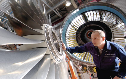
Engines for the A320
Two types of engines can power the A320: the CFM 56-5 or the IAE V2500, both from different consortiums. As for International Aero Engines, the fan (or low pressure compressor) comes from Japanese Aero Engines Corporation, the high pressure compressor from Rolls Royce, the combustor and high pressure turbine from Pratt and Whitney, and the low pressure turbine from MTU Aero Engines. With only a unit of air burnt for every 6.4 units of air sucked in, “IAE ensures the V2500 is able to deliver the lowest fuel burn and best performance retention. The V2500 also boasts of the lowest total emissions, environmental leadership in its class and the lowest cost of ownership”. Each engine delivers a thrust of 11,363 kg.
In an IAE equipped aircraft, engine readings are not as intuitive as their CFM (a 50/50 joint company comprising Snecma of the SAFRAN Group and General Electric) counterparts. With CFM A320s, the fan rotation, or N1, is displayed as a percentage of maximum rotational speed. However, in IAE equipped aircraft, readings are in terms of the pressure ratio developed by the front most section of the engine: the huge air intake fan that is readily visible on the ground. The fan alone can develop an engine pressure ratio (EPR) of 1.6.
With push back complete and a wave to the ground crew, Captain Henry advanced the throttles mildly for taxi. Meanwhile, the checklists were completed and control surfaces checked for normalcy. The A320 lined up on runway 07R, the runway alignment coincidently ideal for its east bound route. Every major airport has a Standard Instrument Departure (SID). This is to ensure that aircraft follow a predetermined flight path and provide better separation between arrivals and departures such that air traffic flow is optimised. Mandala 276 flies to Surabaya via airway W45, through waypoint KASAL, radio beacon CA, waypoint PIALA, radio beacon ANY, radio beacon BA, waypoint NIMAS, before touching down at Surabaya. A quick look at the charts reveals that the SID designated PURWAKARTA2C from runway 07L/R would take Mandala 276 to W45’s KASAL.
The flaps were set to 1+F, a configuration that extends both the flaps and the slats from the wings, by the least increment. The advantage of using flaps and slats is that the aircraft stalls at a lower speed, thereby facilitating lift off at a lower speed and shorter take off roll, a requirement not critical on long runways.
Thrust Dynamics
Simple laws of motion dictate that for a given weight, greater the force on the aircraft, greater is the acceleration and hence shorter the take-off distance. The flip side of this shorter take off is that the engine is operated at its limits. So severe are the stresses that if the engine is run at maximum thrust for 10 minutes, the blades would begin to melt. The Exhaust Gas Temperature (EGT) of jet engine is nearly 600 degrees centigrade. Higher the thrust required, greater is the fuel burnt and hence higher the temperature. When the engine is specified an Outside Air Temperature (OAT) of a particular value, it can be asked to command a thrust such that the EGT for a particular thrust plus the OAT equals the maximum EGT of about 600°C.
A quick mind will immediately see the benefits of such a procedure. A long runway would not require the aircraft to take off in a short distance. This would in turn not require maximum thrust setting on the engines. This would lead to “flexible” thrust: by specifying an OAT that is greater than the actual OAT, the engine is fooled into delivering a lower thrust. Hence, the flexible take off thrust that day commanded an EPR of 1.301 as against the maximum of 1.6 by specifying an OAT of 68°C while the actual OAT was 31°C. Compromise with take-off distance enhances engine life.
Today’s tough competitive environment forces airlines to consider operational costs in every facet of business. The cost of a flight consists of fuel cost, time related costs and fixed costs. In the 1970s, when fuel prices surged and with fuel costs accounting for no less than 45 per cent of operating costs, airlines were worried about fuel consumption. Gradually, as prices eased, airlines began to include other costs into their equation, the only two variables being fuel cost and time related costs.
The Concept of Cost Index
Any attempt to reduce fuel consumption adversely affects time-related costs and vice versa. The faster the aircraft flies, higher is the drag and higher the fuel consumed, but shorter is the time of travel. Thus, time-related costs, such as hourly maintenance costs, flight and cabin crew costs per hour and marginal depreciation or leasing costs, are saved. But the important point lies in incurring the minimum cost for the trip. Thus, the concept of Cost Index (CI) was born.
CI is the cost of time over the cost of fuel. A CI of 100 would imply that 100 kg of fuel is as expensive as one minute of flight time. A higher CI emphasises savings on time-related costs; a lower CI saves on fuel. For a given place, the cost of available fuel is weighed against the cost of time that would be expended. The CI, which would result in the least operating cost due to both time and fuel, would make sense to the airline’s operations. And Mandala 276, for that day was flying with a CI of 39.
As the aircraft accelerated down the runway, a close watch was kept on the airspeed and as it approached 154Kts, the First Officer called out “V1”, indicating that the pilot must, at that very instant, decide to abort or continue with the take-off. Since all systems were normal, the Captain decided to go ahead with the take-off. At 155Kts, the First Officer indicated that the pilot could safely get airborne by calling out “Rotate”. The captain smoothly pulled back on his flight stick, that made the aircraft pitch up and rise.
The most remarkable feature about a new generation Airbus cockpit is the absence of the conventional semi-steering wheel known as the control column. Instead the Airbus has a small stick to the left of the Commander and to the right of the First Officer. Pilots who move onto the new generation Airbus aircraft from conventional aircraft initially do experience a void and have to adapt to the side stick. However, most are all praise for the new technology.
fly-by-wire Technology
The new generation Airbus aircraft differ from conventional aircraft in that these aircraft use “fly-by-wire” technology. Inputs by the pilot are neither mechanically nor hydraulically linked to the control surfaces. Movement of the side stick generates electrical signals representative of the stick position. These signals duly processed by computers, move the control surfaces by hydraulic pressure. The computer between the side stick and the control surfaces limits the pilot’s input such that the aircraft may not perform as the pilot commands. And this is the wonderful feature that prevents modern Airbus aircraft from exceeding safe operating limits. The fly-by-wire system is a result of military technology that, after some diffidence, was incorporated successfully for the first time in civil aviation on the Airbus A320.
With fly-by-wire technology, the pilot cannot, under normal circumstances, bank the aircraft by more than 67 degrees from the vertical, pitch up by more than 30 degrees and pitch down by more than 15 degrees. Besides, all manoeuvres are limited in the stress induced to 2.5G. In the unlikely event of the aircraft approaching stall, the nose is lowered and engines automatically advance to full thrust. In the event of over speeding, the aircraft raises its nose gently. In all these cases, pilot input is smoothly over-ridden in the interest of safety.
As Mandala 276 was airborne, the First Officer raised the landing gear and requested for a direct routing to CA, instead of following the longer PURWAKARTA2C departure. Since there was no conflicting traffic, ATC agreed. The reason for such a request was obvious—flying a shorter distance saves fuel. Suddenly, the Master Caution sounded. Engine number two bleed had a fault. An engine can “bleed” some of its pressurised hot air from the compressor which is used for temperature control, cabin pressurisation and air conditioning. A malfunctioning bleed may prevent the aircraft from climbing to cruise altitude which for this flight was Flight Level (FL) 370 or 37,000 ft above Mean Sea Level (MSL) at a standard pressure setting of 1013.25hPa. Bleed from one engine is incapable of maintaining cabin pressure and hence the aircraft must descend to a lower altitude of 22,500 ft, before the APU’s bleed may be used to compensate for one defunct bleed system.
Most jet aircraft have one more jet engine than is visible to the eye. The twin-engine Airbus A320 has a third smaller engine at its tail known as the Auxiliary Power Unit (APU). This is not used for propulsion, but to augment pneumatic and electric power when needed. Most of the time, engine start on the ground takes place with the APU’s pneumatic pressure. The APU is limited in its altitude of operation to 22,500 ft. In case both the engine bleeds malfunction, the aircraft needs to descend to 10,000 ft—an altitude at which the cabin need not be pressurised. However, with APU available to compensate for the loss of both engine bleeds, the aircraft can carry out emergency descent to 15,000 ft. If the requirement is limited to electrical power, the aircraft need not descend below 25,000 ft MSL. Mercifully, after repeated recycling, the faulty bleed system became functional before reaching FL370.
SP's AirBuz - CURRENT ISSUE